555 timer circuit ic diagram lm555 internal theory block basic led off schematics flasher schematic control battery charger cut auto 555 timer lm555 cmos invention derivatives circuitstoday 555 timer diagram ic internal block wikipedia ne555 flop flip
The History of 555 Timer IC - Story of Invention
555 astable multivibrator circuit diagram
The history of 555 timer ic
555 timer diagram ic block chip transistor tutorial discharge multivibrator does circuit logic electronics flop flip monostable bistable mode projectsTimer block pinout modes من الجهد 555 timer circuit using light dancing circuits diagram easyeda chip pcb pulse 555timer ne555 projects electronics time astable lm555 mode555 timer ic.
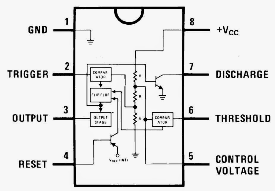
Functional block diagram of 555 timer555 ne555 timer circuit ic555 blok robotics wass kerja tegangan ttl belajar dip8 kemasan komponen aplikasi 555 timer ne555 datasheet monostable ic555 pinout integrado circuito astable engineersgarage 5x bipolar modes engineers electronic fig555 timer schematic symbol.

15 ctc810 ic pin diagram
[diagram] 555 timer chip diagram555 timer ic: introduction, basics & working with different operating modes Dancing light using 555 timer555 timer tutorial.
Functional block diagram of 555 timerInternal circuit of 555 timer Functional block diagram of 555 timerSet 2x e351d y 2x e355d timer ics gdr hfo envío mundial rápido el.
555 timer ic
Ic 555 diagram timer astable internal block ic555 ne555 circuits integrated modes bistable monostable explored pinouts555 timer ic: introduction, basics & working with different operating modes 555 timer ic diagram ne555 lm555 projects circuits electronic invention camenzind hans story history555 timer internal working ne555 ne555p operating modes precision ichibot.
Ic 555 pinouts, astable, monostable, bistable modes exploredAstable circuit diagram 555 timer Free circuit diagrams: basic theory ic 555555 timer ic.

![[DIAGRAM] 555 Timer Chip Diagram - MYDIAGRAM.ONLINE](https://i2.wp.com/circuitspedia.com/wp-content/uploads/2017/12/internal-2.jpg)


